
Exploring the 1914 Kissel 4-40 Electrical System
 |
 |
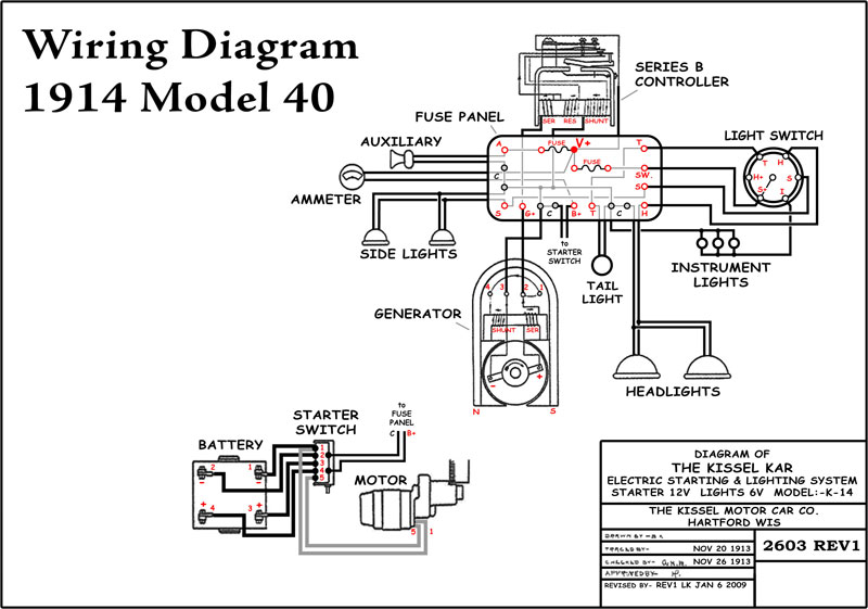
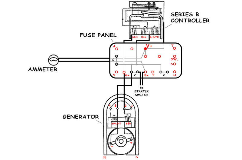
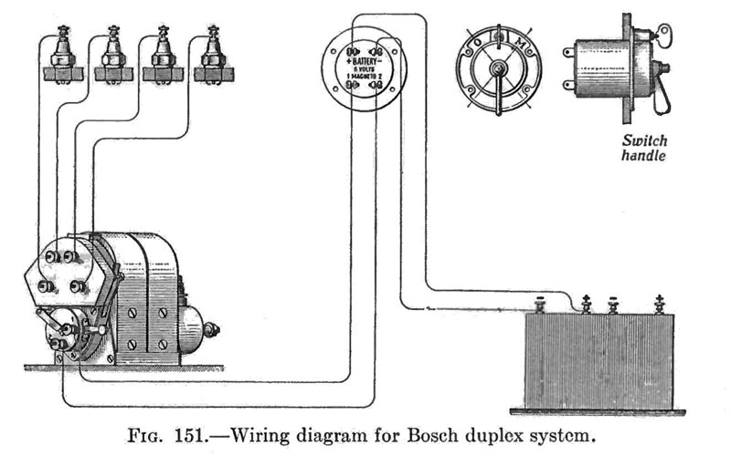
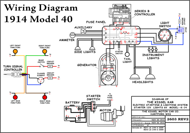
| A redrawn diagram of the starting-charging-lighting system from the 1914 KisselKar Instructions (left, click here for a 0.2MB version). The Bosch "duplex coil" ignition system from Gas Engine Ignition (right). | |
| Jump to: | |
| Lynn Finds an Easter Egg | |
| Overall Description | |
| Starting Circuit | |
| Charging Circuit | |
| Lighting Circuit | |
| Ignition Circuit | |
| Possible Safety Enhancements | |
Andrew Wilson and Lynn continue to exchange information via email about their 1914 KisselKar 4-40 automobiles. Recently Andrew is sharing details of Herman's electrical system and Lynn is studying the information and comparing it with what he's found on Annie during his recent trip to Hartford. As with the study of the transmission, Lynn is surprised how much he's been able to learn with Andrew's help.
Andrew provides a critical piece of information, a higher resolution scan of the wiring diagram from the 1914 KisselKar Instructions. Lynn studies this diagram carefully, and uses Adobe Illustrator and Photoshop to redraw the diagram. The result of Lynn's effort is the lead image at the top of this page.
Lynn Finds an Easter Egg
 |
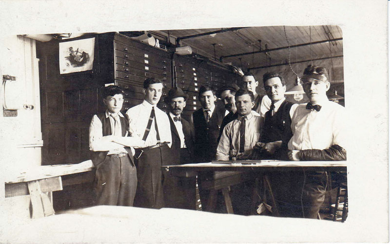 |
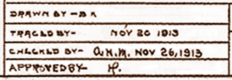
Herman Palmer's initials in the approval box of the drawing (left). Herman Palmer was Kissel's chief mechanical engineer. In this 1915 picture (right), Herman the one in the hat, third from the left.
|
|
Every now and then, Lynn stumbles across something he calls an easter egg while working with his old cars. By this he means something that has laid hidden for years which is suddenly and unexpected revealed to his delight. It is usually a small thing. Most people may be largely unimpressed, but through it he suddenly feels a connection with people from another place and time.
The two easter eggs that come to mind with Bugsby are the single Edison plug he found in the head, and the Australian Florin he found on the flywheel.
While working with the digital image of the 1914 wiring diagram, Lynn suddenly recognizes the stylized initials in the approval box are almost certainly those of Herman Palmer, Kissel's chief mechanical engineer. The second vertical stroke of the H is combined with the vertical stroke of the P to form a symbol that looks more like a glyph or rune than initials. Without his recent association with Andrew and his car, Herman, the significance of these initials would have been completely lost on Lynn.
Overall Description
With explanations from Andrew and selected pictures from Herman, Lynn begins to make sense of Annie's electrical system, at least as it was originally designed by Kissel.
One interesting fact is that these electrical circuits are return earth systems. Unlike most modern vehicles, the chassis is not used as an electrical conductor or ground (or earth) for the circuits. The negative, return-current portion of every circuit is carried by a dedicated wire.
From Lynn's perspective, the diagram can be logically broken into three chunks:
- The starting circuit (6/12V battery, starter switch and starter motor);
- The charging circuit (generator, ammeter and controller); and
- The lighting circuit (lamps, accessories, light switch and fuses).
It takes Lynn some time to recognize that nowhere in this diagram is shown the ignition circuit. It is a completely separate electrical system and not connected with the starting/charging/lighting circuits in any way.
Starting Circuit
 |
 |
 |
 |
|
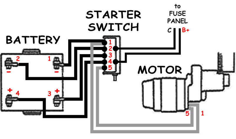
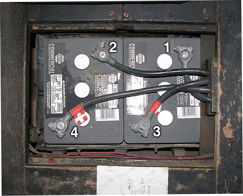
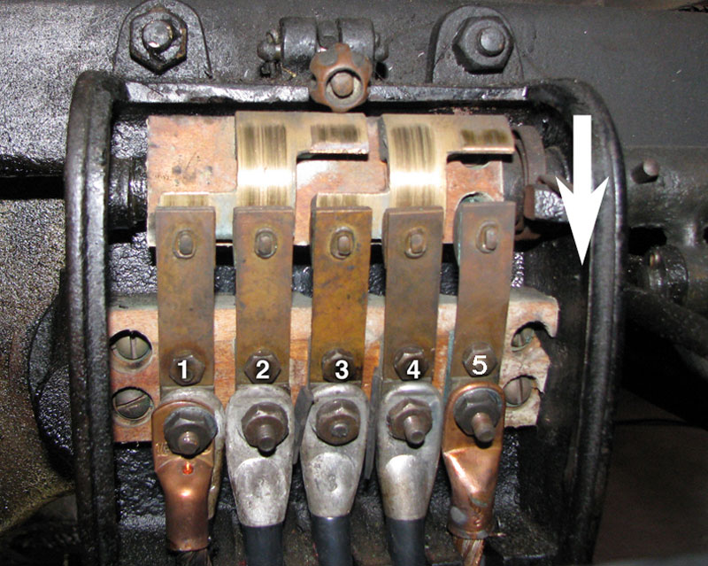
The starting circuit consisting of batteries, starter switch and starter motor (left). In Herman, the posts of two 6V batteries (left-center) are connected to the starter switch (center-right). The massive starter motor on John Quam's car (right). (photos of Herman courtesy of Andrew Wilson)
|
||||
The factory original 1914 KisselKar 4-40 battery was a four terminal battery which was essentially two 6V storage batteries in a single case. Andrew Wilson uses two 6V storage batteries (NAPA part number BAT 7244) as shown above.
In normal 6V operating mode, the starting switch is positioned as shown in the photo above; cables 1 and 2 are shorted together; cables 3 and 4 are shorted together. That is, the negative terminals of the two batteries are connected to each other, and the positive terminals of the two batteries are connected to each other. As a result, the batteries are connected in parallel and there is nominally a 6V potential difference between terminals 2 and 4 of the switch. Terminals 2 and 4 are connected to the 6V generator and 6V lighting circuits via the fuse panel.
In 12V starting mode, the contacts of the switch rotate in the direction of the white arrow shown in the photo. Now cables 2 and 3 are shorted, and cables 4 and 5 are shorted. That is, the negative terminal on one battery is connected to the positive terminal of the other battery. As a result, the batteries are connected in series and there is nominally a 12V potential difference between terminals 1 and 5 of the switch. As a result, 12V is applied to cables 1 and 5 of the starter motor.
In the 12V starting position, terminals 2 and 4 are disconnected with the 6V generator and 6V lighting circuits. Andrew has confirmed that the vehicle lights go out when the starter switch is engaged.
Charging Circuit
 |
 |
 |
||
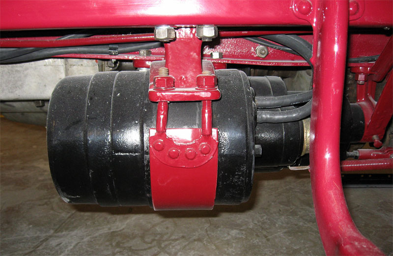
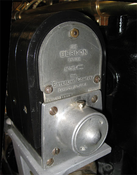
The charging circuit consisting of generator, ammeter and controller (left). The Esterline E-6 generator on John Quam's car (center) and the fuse panel and controller on Annie (right).
|
||||
The generator is used to power the lights and to replenish the energy stored in the batteries. The points labeled V+ and C in the diagram above are essentially the voltage supply points for the lighting circuit, discussed in the next section. The point C is the common (ground, negative) reference point for the circuits. On a more modern vehicle, C would be connected to the metal chassis of the car, but on Annie it is not.
If the voltage output by the generator (between points G+, C) is sufficiently greater than the voltage supplied by the battery (between points B+, C), then the controller connects the output of the generator G+ to the voltage supply point V+. In this situation, the generator is supplying the power for the lights and other accessories. Since the voltage supplied by the generator is greater than the voltage from the battery, current flows from V+ through the ammeter to the battery, charging the battery. The ammeter shows a positive reading (battery is charging).
If the voltage output by the generator (G+, C) is not sufficiently greater than that supplied by the battery (B+, C), then the controller disconnects the generator output from V+ and shorts the generator output to C through the SHUNT, essentially removing it as a power source from the lighting circuit. In this situation, the battery is supplying power through the ammeter to the voltage supply point V+. The ammeter shows a negative reading (battery is discharging).
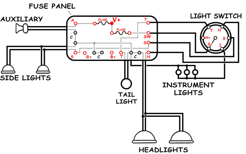
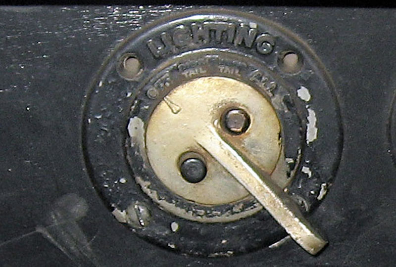
Lighting Circuit
 |
 |
||
The lighting circuit consisting of lamps, accessories, light switch and fuses (left). The light switch on Annie (right). The outer lever controls head/tail/cowl lights. The black push buttons toggle the instrument lights on and off.
|
|||
As noted in the previous section, the points labeled V+ and C in the diagram above are essentially the voltage supply points for the lighting circuit. Either the generator or the battery maintains the voltage difference between these points which is nominally 6V.
There are two fuses on the fuse panel. One fuse is dedicated to the horn. The other fuse is connected to the voltage supply for the lighting switch.
Ignition Circuit
 |
 |
 |
 |
||
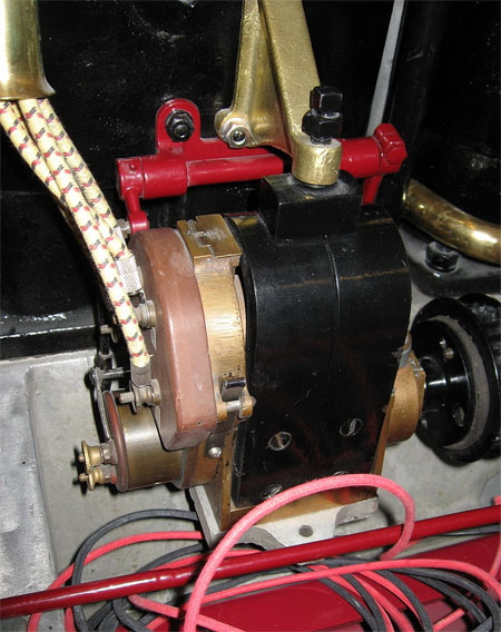
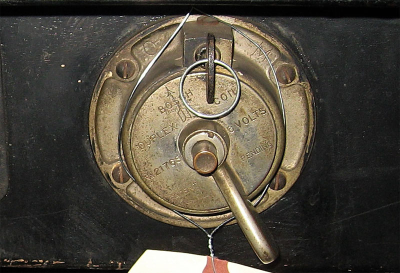
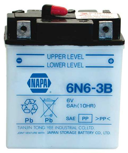
The ignition circuit consisting of spark plugs, duplex-coil magneto, ignition switch and battery (left). The duplex-coil magneto on John Quam's car (left-center) and the ignition switch on Annie (center-right). A NAPA PSB 6N6-3B motorcycle battery is used as the ignition battery by Andrew Wilson in Herman (right). This is a small battery, 3-7/8" L x 2-1/2" W x 4-3/8" H.
|
|||||
As noted above, it takes Lynn some time to realize that nowhere in the starting/charging/ lighting diagram is shown the ignition circuit. Eventually Lynn recognizes that the ignition is a completely separate electrical system which is not connected with the starting/charging/lighting circuits in any way.
Lynn is astonished to find a 1916 book on-line that has a section that details the operation of the Bosch duplex-coil ignition system. In addition to a lucid explanation of the operation of the system, it has a great illustration which Lynn extracts, above.
A typical high-tension magneto ignition system is a completely self-contained engine ignition containing generator, coil, interrupter and distributor. It requires no external source of electrical power. The "ignition switch" on such a system simply grounds the primary circuit of the magneto when switched to the off position which kills the spark and stops the motor.
There is one disadvantage to a magneto ignition system, over a more modern battery and coil system, that may owners of lawn mowers, leaf blowers and old cars can relate to. The generator portion of the magneto requires the engine to turn to generate a spark. The faster the engine turns, the hotter the spark output by the magneto. At low speeds, such as when the engine is being cranked to start, the spark can be weak.
The Bosch duplex-coil ignition system attempts to overcome this disadvantage by using an external battery to supplement the current in the primary circuit of the magneto at low rotational speeds. Once the engine "fires" and spins faster, the battery supplement is no longer needed as the internal output from the magneto is now much hotter than that supplied from the battery.
WARNING! Magnetos use permanent magnets. If the external battery used with the Bosch duplex-coil system is installed with the wrong polarity, the current flows through the magneto in the wrong direction, destroying or seriously degrading the field strength of the permanent magnets.
Ann Klein (former owner of Annie) wrote a narrative that mentions use of a 6V dry cell for the ignition that was housed under the drivers seat cushion. Currently Lynn finds the leads but no battery in Annie.
Andrew Wilson says that when he was 5 years, he remembers his grandfather using a large 6V dry cell under the seat, and that it needed to be replaced often. Currently, Andrew uses a 6V motorcycle battery (NAPA part number PSB 6N6-3B).
Possible Safety Enhancements
 |
 |
 |
|
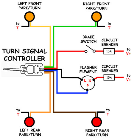
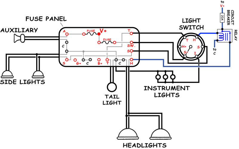
Lynn is considering some reversible modifications to the wiring of Annie (left, click here for a 0.2MB PDF version). One modification is the additional of a signaling circuit and lamps (center). A second modification is installation of a relay and higher power bulbs for the headlights (right).
|
|||
In the fullness of time, Lynn has a goal of touring with Annie. As she is currently configured, Lynn would be afraid to venture out onto California streets with her. Lynn wants stop lights and brighter headlights at a minimum. While he's at it, he might as well add turn signals and four-way flashers.
Lynn has found that motorcycle signal lamps come in a wide variety of shapes and sizes, and ones can be found that are relatively unobtrusive. He searches the extensive listings on ebay and gets relatively inexpensive amber-lensed ones for the front, and matching red-lensed ones for the rear. Standard 6V 1154 dual filament bulbs can easily be substituted for the 12V 1157 bulbs that are typically installed.
Seven-wire turn-signal controllers are readily available from a variety of sources on-line.
The original headlights on cars of Annie's vintage are notoriously poor as judged by modern standards. Andrew says that his grandfather would say that the lights on Herman were so dim that he had to get out of the car and use a cigarette lighter to check and see if the lights were working.
Plug replaceable higher wattage headlight bulbs are available. One problem with simply replacing the bulbs is that the higher current drawn by the lights can burn the contacts on the light switch. By installing a relay, the switch need only handle the small current needed to control the relay while the relay switches the large current to the headlights.
Lynn intends to add these items in such a way that they can be easily removed so that the car can be quickly restored to an original configuration for car shows. The wiring modifications will be segregated from the original wiring and can be easily reversed it needed.
 |
|||
There is likely a convenient place to unobtrusively mount a mechanical brake switch under the floor boards of Annie.
|
|||
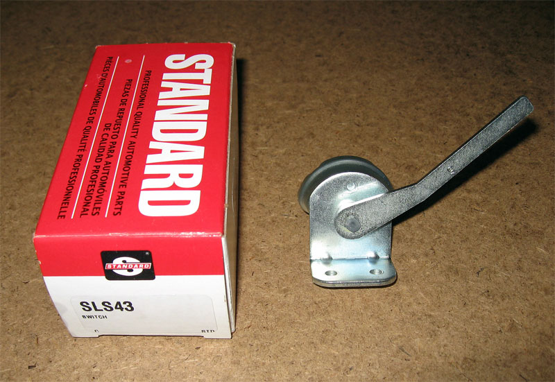
Lynn had successfully used a Standard SLS43 mechanical switch (from a mid-1950's Chevrolet truck) on Bugsby and Penny. There is also a Standard SLS40 switch (from an early 1950's Chevrolet truck) that is the mirror image of the SLS43. Where the photo above shows the arm of the SLS43 extending to the right, the arm on the SLS40 extends to the left — this difference might be useful for some installations. The SLS43 is also a little cheaper than the SLS40.
Lynn plans to follow the lead of Andrew and use a motorcycle battery for the ignition. Lynn is wondering if this battery couldn't also be connected to the (B+, C) terminals of the fuse box. He has some concern about damage to the magneto so he won't do this immediately, but it seems like it could be safely done, based on what he currently knows about the electrical system. If the connection is safe, then the ignition battery could supplement the main storage batteries for lighting and be automatically recharged by the generator.
Contact
 with your comments or questions
Copyright © 2018 Lynn Kissel
Last updated: May 24, 2009